To see how lasers are used in telecommunications we first need to examine the field of telecommunication as a whole. Today, almost all telecommunication occurs through transmission of electromagnetic waves from a transmitter to a receiver. These transmitted waves range in frequency (or, if you like, in wavelength) from visible light to microwave to radio wave signals. Whatever wavelength of electromagnetic wave that is sent out from the transmitter station, all of these share a common set of techniques for combining the signal that is to be transmitted, with the carrier wave that "moves" the signal from one location to another.
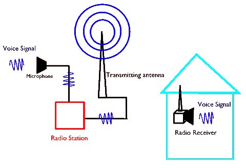
Most often the signal to be transmitted is a voice or a video signal that can be converted into a single variation of some sort, say a voltage variation, as a function of time. In the case of voice, for example, a sound wave in air at a microphone receiver generates a changing voltage that is a duplicate of the original voice (in the sense that it contains the same information). That is to say, the signal itself is just a wave and so, can be represented by amplitude and frequency variations. All that we need to do is to somehow incorporate these amplitude and frequency variations into the amplitude and frequency variations of the carrier wave (an electromagnetic wave) to send it long distances . In practice this is done either through analog or digital encoding. The following sketch shows an announcer's voice signal entering a microphone in a radio station. This signal is encoded on a carrier electromagnetic wave which is broadcast by the transmitting antenna. In our home, our radio receives the modified carrier wave and extracts from it the variations that were encoded on it. These variations are then fed into the radio's speaker that then generates a duplicate of the announcer's voice.

In the case of analog encoding, the variations of the signal are incorporated so as to cause a change in the actual "shape" of the carrier wave. There are two common methods employed for this purpose: Amplitude Modulation (AM), and Frequency Modulation (FM). In contrast, in digital telecommunication the carrier wave's does not change frequency or amplitude; instead, its broadcast and lack of it are used, as a binary code, to transfer information. This is done in a variety of ways, from pulse rate modulation to pulse shape (width) modulation, to pulse position modulation, etc.
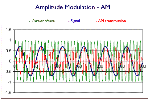
The above picture shows transmission of a very simple signal, a regularly varying wave that might be a single pitch sound, for example, via an amplitude modulation of the carrier wave. The transmitted signal (depicted in red) is the same wave as the carrier wave, but its amplitude varies according to the variations of the signal wave.
Exercise: draw the same carrier wave, as in the above diagram, but now make the signal's amplitude change (say, modeling a single pitch sound that changes loudness). Then draw how this modifies the amplitude modulated transmitter wave.
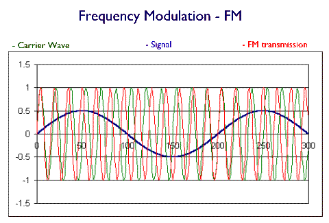
In the frequency modulated wave (FM) changes of frequency and amplitude of the signal are incorporated as frequency changes of the transmitted wave. Again, for a simple single frequency and fixed amplitude signal, this is shown in the sketch below:
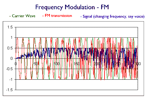
The following diagram shows amplitude modulated transmission of a signal whose frequency and amplitude are changing. Please note that on all three of these diagram the horizontal axis shows the time.
This difference in encoding the signal either as amplitude modulation (AM) or frequency modulation (FM) of the carrier wave results in rather practical implications for a broadcast. In the case of AM broadcast the frequency of the transmission is fixed. This means that, assuming accurate transmitters and receivers are available, a single frequency can be used for transmission, say for a radio station. A frequency range (called a band) is allocated for transmission of many different broadcasts. In the case of radio transmissions, then, the Federal Communications Commission (FCC) allocates a large number of radio stations to a narrow band of AM transmission frequencies. Another band is allocated for CB (Citizen Band) transmission, etc. As for telecommunications via a wire (telegraph or telephone) or cable (video) this means that for a range of frequencies many transmissions can be sent simultaneously. Of course, the wider this frequency band, the larger the number of simultaneous transmissions.
In contrast to this, FM broadcasts require an allocated transmission frequency band per broadcast. This limits the number of simultaneous transmissions. On the other hand, it leads to a cleaner signal because as a electromagnetic wave travels its amplitude degrades far more easily than does its frequency. Most materials (through which electromagnetic waves travel) can easily absorb the wave energy, so they can damp the wave's amplitude. But to alter the frequency of an electromagnetic wave that passes through a medium another wave would need to be created to interfere and thus change the frequency of the traveling wave. As a consequence, AM waves degrade far more easily than do FM transmissions. So, for the same transmission power at a radio station, FM signals tend to be "cleaner" and less "noisy" when received by our radio tuner. In the case of radio transmission, atmospheric effects, such as weather changes or the presence of charges particles often sent to the earth from solar flares, produce the unwanted noise. Other sources of radio noise are reflectors, such as clouds, airplanes, or buildings. In wire or cable broadcasts atmospheric effects can also play a role, but most of the noise tends to come from other transmission sources either in the same wire or in a nearby one.
A more effective method of reducing noise in the transmitted signal is to send a digital broadcast. In a digital broadcast all that is transmitted is a binary code that represents the signal that is to be sent. This encoding is done by first sampling and converting the analog signal into a series of numbers. For example, voice signal fed into a microphone produces a voltage variation. Values of this voltage are sampled and recorded at regular time intervals. These values are then sent as numbers to a distant receiver which generates a duplicate of the original voltage values based on the numbers it receives. This duplicated set of voltages is used to drive a speaker and produce a "copy" of the original voice signal. So, in digital transmission the waveform is not transmitted, but rather just a set of numbers that represent the waveform.
What makes digital broadcasts clean and noiseless is that the values representing the waveform are sent in binary. Each of the values is converted from a base 10 number into a number of base 2, i.e. a binary representation. A base 2 number is a string of zeros and ones. The location of these zeros and ones in the string signify the power of 2 while the actual value of zero or one signify whether such power is to be taken into the calculation (one) or not (zero). For example, the string: 010 means that in this number (010) there is no two-to-the-power-0 or 20, nor two-to-the-power-of-2 or 22, but there is one two-to-the-power-of-one or 21. So, this number is 0 x 20 + 1 x 21 + 0 x 22, or just the number 2. We can think of this binary string as a set of bins that range in value, from right to left, in increasing powers of two. The bin is "empty" when it is represented by 0 and it is "full" when it is represented by a 1. Below is a string with 5 bins:
|
24 = 16 |
23 = 8 |
22 = 4 |
21 = 2 |
20 = 1 |
So, a string of five binaries (0s and 1s) can represent any number from 0 (that would be the string 00000) to the number 11111= 16+8+4+2+1= 31. The number 9, for example, is then 01001; the number 5 is 00101; and the number 25 is (16+9=16+8+1) 11001 and so on.
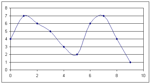
Consider the signal shown in the above graph. This signal is sampled at ten equal time values (horizontal axis). At time zero, its value is 4, at time 1 its value is 7, etc. The following table shows the values of the signal at these ten samples along with their binary representations (please note that because the largest value is 7, we only need a string of three bins):
| Time | Value (regular - base ten- representation) | Value (binary - base two - representation) |
| 0 | 4 | 100 |
| 1 | 7 | 111 |
| 2 | 6 | 110 |
| 3 | 5 | 101 |
| 4 | 3 | 011 |
| 5 | 2 | 010 |
| 6 | 6 | 110 |
| 7 | 7 | 111 |
| 8 | 4 | 100 |
| 9 | 1 | 001 |
The clear advantage of the binary representation is that we now need to send strings of zeros and ones, instead of a string of number values. So, instead of having to change the amplitude or frequency of the carrier wave all we need to do is to send (on = 1) or not to send (off = 0) a signal. This signal, for example, could simply be the peak of the carrier wave. How high this peak is (i.e. what amplitude it has) doesn't matter, so long as our receiver can detect a peak. That is to say, any distortions of the carrier wave that changes its amplitude and frequency, but still allows a peak to remain a peak will not degrade the signal. In practice, there is a sensitivity level of the receiver, called the threshold, above which any signal is interpreted as "on", and below which it is considered to be "off". If the carrier is distorted so that a peak value falls below the threshold, then an "on" is read as "off" and this will clearly affect the integrity of the signal. It is because of this factor that noise will either have no effect on the quality of a digital transmission or it will ruin it altogether - it is an all or nothing effect!
The following , composed by Jennifer Sweeney, a former student in this class (Spring of 1993), describes this process poetically:
Questions on Telecommunications
Optical Fibers & Telecommunication
As we discussed in the section on reflection and refraction of waves, when a ray strikes an interface from a region of higher index (say water-to-air) above the so called critical angle, it will undergo total internal reflection. This is the principle behind the operation of optical fibers. Optical fibers are very thin strands of glass (silicon oxide) or plastic. Ideally, light that is fed into one end of the fiber undergoes total internal reflection every time that it strikes the sides of the fiber, and ultimately exits the other end of the fiber. In practice, of course, some light will get lost out of the fiber for light rays that strike the sides at angles smaller than the critical angle, but most of the light gets through even for reasonable lengths of the fiber. These light guides are also referred to as "optical wave guides".

In the above picture the red colored ray passes through (is guided through) the fiber, but the green ray strikes the fiber-to-air interface at an angle smaller than the critical angle and therefore exits the side of the fiber and is lost. In addition to losses due to a large angle of incident light coupled into the fiber, the intensity of light can get diminished because of absorption within the fiber or at the interface. To reduce absorption losses at the interface the fiber is covered with a layer of glass that has a lower index of refraction than the inner core glass. This layer is called the cladding. Another solution for preventing absorption losses is to use light of a wavelength that does not get absorbed by the glass or plastic. Since the primary impurity in a fiber is water molecules, typical wavelengths of 1 or 2 micrometers work well and do not get absorbed by the water. Ultimately, small losses arise from light scattering from imperfections in the glass but light signals can propagate for over a hundred miles without amplification and still be clearly detected.
Optical fibers were first made in the 1950's, but the quality of the materials limited transmission to tens of meters. The industry of optical fibers has developed extensively particularly since the production of inexpensive semiconductor lasers and better glass materials became possible. Most of this development has been driven by the need for data transmission for voice, video, and computer network signals, such as those on the World Wide Web. But fiber optics have also been used in imaging and laser light delivery applications, especially in medicine. Coherent fiber bundles are routinely used by surgeons to image internal parts of the body and for delivering and manipulating laser light for internal surgery.
Optical fibers come in a variety of designs. Standard fibers have a uniform index of refraction within their cores. The drawback of this simple design is that rays that strike one end of the fiber at different angles end up getting out of the other end at different times (why?). As a result, a pulse that is sent through such a fiber ends up having large distortions when it leaves. To reduce this distortion, fibers are manufactured so that the index of refraction of the core decreases in value from the center axis of the fiber outwards. Because the speed of light increases with lower index of refraction, the off-axis rays tend to travel faster (albeit more wavy and thus longer paths; see the green ray, below) than the axial rays (blue color ray , below). The net effect is that the rays entering the fiber at different incident angles exit the other end at nearly the same time. This type of fiber is called a graded index fiber.

For many applications what matters is how much light gets through the fiber. When wavelength distortions are not an issue, a multimode fiber is used. These fibers have core diameters of tens of microns. This is in contrast with single mode fibers that have core diameters that are smaller than 5 microns. Still another method that is used to fight signal losses in the fiber is to use repeaters. These are basically receiver-amplifier-transmitters. Since digital information requires transmission of a binary code, all that the receiver needs to "understand" is the "zeroes and ones". In the case of pulsed signals, for example, the presence of a pulse is a "one" and its absence is a "zero". So, the receiver could simply be a photo-detector. When it detects a pulse it sends a signal to a new pulse generator that will now send a stronger pulse down the length of the fiber. In this way the repeater changes the "dim" pulse that it received into a "brighter" one, which it sends out. This is shown for two fibers in the sketch below. Typical detector/amplifier systems use erbium-doped fibers and diode lasers which act as pumps to amplify the weak input signals as shown in the scheme below. The underwater cables that run between North America and Europe have optical fibers with many repeaters. These battery operated repeaters allow the signal to travel coast-to-coast with virtually no distortion.
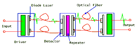
Fiber optic repeater scheme

Fiber optic amplifier using an erbium-doped fiber and diode laser pump
What makes optical fiber technology so very useful in telecommunications is that light is the signal working at carrier frequencies of 1014 Hz. In the case of voice transmission, for example, the signal to be transmitted has frequencies that may range from tens of Hz to 10,000 Hz. Let us say, for now, that we want to transmit a 10,000 Hz frequency sound wave. This means that we need to encode a wave that varies in frequency 10,000 times per second. If we sample this wave 100 times in one of its periods, this requires a sampling rate of 100 x 10,000 = 106 Hz. Now, to encode these sampled values we need a string of binaries. The size of this string depends on how much precision we want to include in the values of the 100 points that we sample from our wave. We saw, above, that a string of three binaries can encode 8 numbers (0,1,2,3,4,5,6,7). In our case, let's say that we need a string of 10 binaries. This would allow us to encode a great deal of precision in our signal. With this choice, then, all we need is a carrier wave that has a frequency of 10 x 106 = 107 Hz (or a bit rate of 10 Megacycles). So, with a fiber optic we could send 1014/ 107 = 107 such signals simultaneously! In contrast, a cable transmission wire, of the type that cable TVs use could handle a transmission frequency that is, at best, 1 GHz = 109 Hz. This would allow simultaneous transmission of only 100 of our signals. In practice fancy mathematical algorithms allow engineers to use compression techniques to send smaller signals that require far smaller bit rates than our estimated 107 value. This is why we can still get by using cable technology. But based on most projections, we will soon need to switch into the higher transmission frequencies allowed by optical fibers. For a short discussion on this and different state-of-the-art fiber technologies visit Corning's Web site.
Here is still another poem!
Fibre Optics
by long-distance fibre optics.
Again a call from an old friend I thought I'd lost,
the name sheepishly uttered, the pause, the rush
of joy liquefying the wires:
the long draft imbibed, savored,
of common names, Albert's mother's remarriage, Sandra's
promotion, Jeremiah-when did Jeremiah change his name to
Steve? And the flow of explanations
into which we dip-of home, of work, of love,
how it's a mere mockup of a river, a silvery ether
made of tinfoil shaken by Props from the wings of stage,
not a real river, not real life,
but that doesn't explain why
we never talked till now. Why now? Why not next year?
Certainly it's as if nothing had changed; we swim smoothly
through years and jobs and days, drifting back
to the familiar waters of our estrangement
only when you go off to fetch your address book.
How hard the ear works to make out the background noise,
the clink of the coffee mug, the chatter of Sunday papers,
how hard it presses against the ear-warmed disk
to discern-what? The click of a hanger emptying
its mundane load? The VCR switching on by itself?
How weary the sounds that stumble across the wire-
the old address penciled out, the new address
penciled in - and everything clear,
static-free, instantaneous, flowing true,
by David Woo (published in New Yorker Magazine, cc 1990s)
Another optical communication system that has received renewed attention is atmospheric optical communication. In this system the optical signal is sent directly in the atmosphere, requiring no physical links (using cables or optical fibers) between the transmitter and the receiver. Because of atmospherics changes caused by weather conditions, this system is most useful for short distances and where installing fibers or cables is costly. The need for more cell phones has saturated radio frequencies.

One way to alleviate this problem is to free-up radio bands reserved for other data communications, such as computer data transmissions. Because of this, atmospheric optical communication is becoming more and more popular for inner city high density data communication. In a typical system of this type a standard fiber optic or satellite transmitted signal is carried to a tall central building. This signal is used to modulate lasers aimed at receivers located on roof-tops of neighboring buildings. Each receiver then uses conventional cabling/fiber to distribute the signal to the many users in its building.
