Light as a Wave
All waves exhibit both reflection and refraction properties. When a wave moves from one medium into another, its direction of propagation changes; this is termed refraction. In addition to the transmitted wave continuing from one medium into another, there is also a reflected wave back into the original medium. For example, when your radio is playing music in your room, the sound waves pass through the walls as well as reflect from them. Similarly, some of the light from your lamp passes through the glass of the window in your room, and some also is reflected from the glass. The fractions of the wave intensity (related to the wave amplitude) that reflect and transmit have to do both with the type of the wave and with the materials that make up the media. Some examples will illustrate this. The room walls do not allow any of the electromagnetic waves in the wavelength region of the visible light to transmit, so most of the light reflects off the walls (some also gets absorbed). But electromagnetic waves in the radio frequency region easily pass through the room walls - as you know since they can get to a radio antenna even when inside a house. Similar to radio waves but unlike visible light, sound waves pass though the walls, but unlike the radio waves they lose a great deal of their intensity and only muffled sounds will pass through. When sound passes through glass, however, it is attenuated far less. On the other hand, neither visible nor radio waves pass through metals, but sound waves do.
Our primary concern, in this section, is the change in the path of propagation of light as it transmits and reflects. For this reason let's consider electromagnetic waves in the visible region, i.e. visible light. Collimated light, just as in a laser beam of light, was constructed using sun light and a pin-hole almost a thousand years ago. This was given a name: a ray, which (in Arabic) means a strand. The Iraqi born scientist, Al Hazem, discovered back around 900 AD that when a ray of light passed from air into glass part of it reflected and the part that was transmitted did so but sharply bent as it entered the glass. This bending, which occurs right at the interface (boundary) of air-to-glass, is called refraction. Al Hazem further quantified these effects to discover that light reflects from the interface in a manner very similar to how a ball gets "reflected" off a wall as it strikes it. That is to say, the angle that the ray makes with a perpendicular to the wall is the same both for the incident (striking) ray and for the reflected one. The refracted ray bends by an angle that depends on the ratio of the speed of the light in the transmission medium to that in the incident medium. The greater this ratio, the larger the bending angle. So, for example, a ray going from air into glass will bend far more than when it goes from glass into water. At both interfaces, however, it reflects according to the law of reflection: angle of incidence equals angle of reflection.
The above picture shows a ray of light (red lines) striking the air-glass interface from the upper right, transmitting into glass, and then striking the glass-water interface. Notice that at each interface some of the ray reflects. Also notice that when light travels from air into glass it bends toward the perpendicular line to the interface (dash-dot line), and when it goes from glass to water it bends the other way. For light the amount of bending is determined by what is called the index of refraction. The index of refraction, n, is a measure of the speed of light in that medium; it is defined as the ratio of the speed of light in a vacuum, c, divided by the speed in the actual medium - always a slower number - and so the index of refraction is always greater than the value 1. Some example values are: n = 1 for vacuum and nearly so for air; n = 1.33 for water; n = about 1.5 for glass. When light travels from a medium of smaller index into one of larger index (as when from air-to-glass) it bends "in"; otherwise it bends "out". Assignment: take a glass of water and drop a small object in it , say a coin. When you look at the object from above, so that the light from it reaching your eye passes the water-air interface at an angle other than the vertical, does the object appear nearer or further away than it really is?
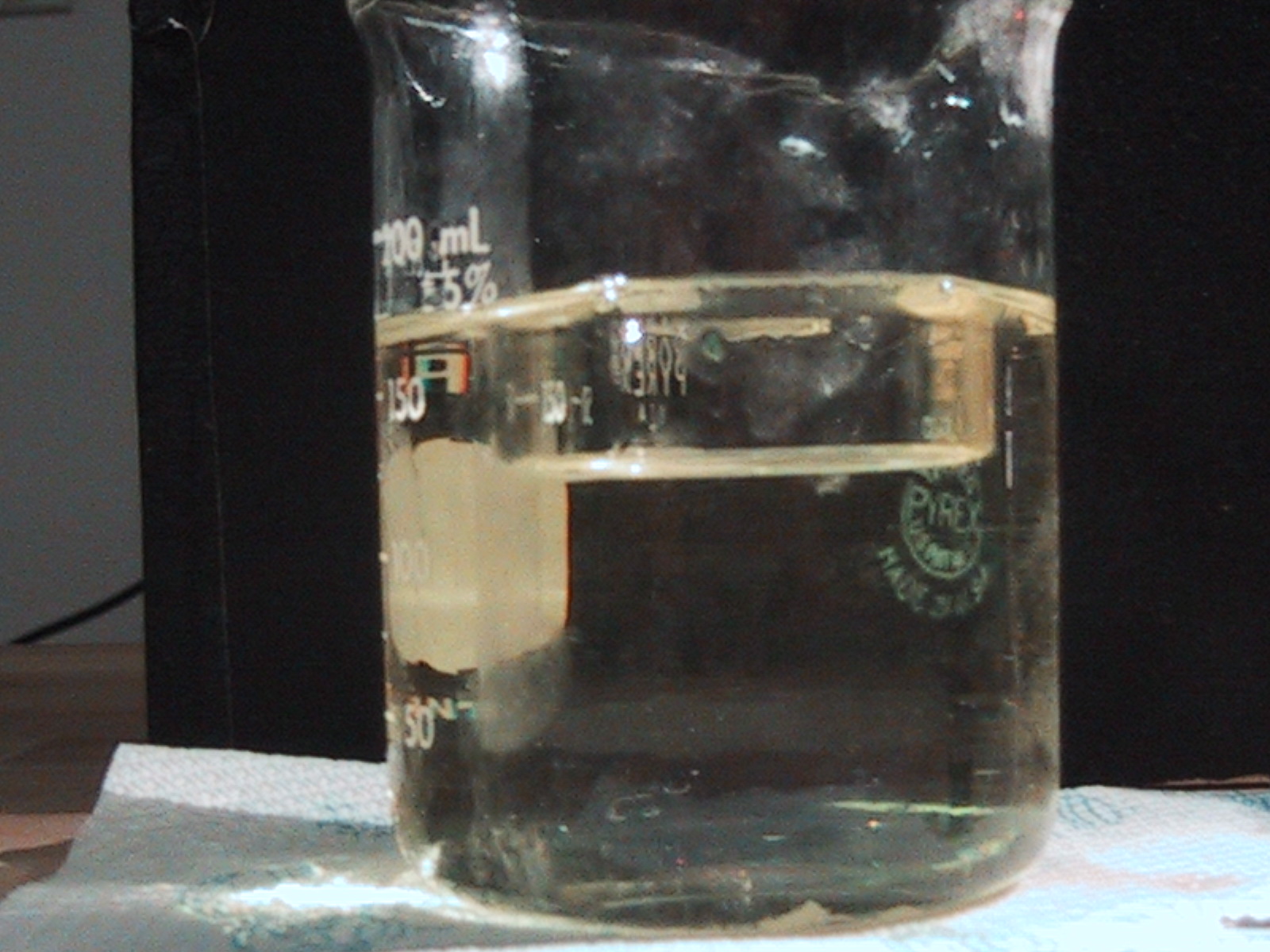
Index-matching: The beaker contains another smaller beaker, visible near the middle of the picture where there is no oil inside to match the index of refraction, but "invisible" where it is filled (inside and out) with oil with a refractive index matching that of the glass.
Waves have no preferred direction of propagation, so light that travels one path will, when reversed, follow the same path in the opposite direction. For this reason, it is not necessary to place an arrow-head on a ray in the above diagram. That is to say if the ray were to be shining from the water side, it would refract through the glass and the air in the same way as it would when it goes from air-to-glass-to-water. (Of course, the reflections would be different!) This property is called reciprocity.
As far as the reflections off the interface are concerned, all that the above diagram shows is the direction of the reflected rays. There is more information that is not shown! First, the intensity of the reflection varies, depending on the nature of the two media as well as the angle of incidence of the light. Second, the phase of the wave may or may not change as it is reflected from the surface. If the wave is traveling from a lower index material into a higher index medium, then the reflected wave changes phase and "flips over" as shown below. Otherwise, the reflected wave does not change phase and reflects back keeping its shape intact. This happens the same way for light as it does for a wave traveling along a string, depicted below:
The top two drawings with black arrows show an incident wave pulse propagating from left to right on a lighter string. Once this pulse strikes the thicker string, some of it transmits, without any change in phase, while the remaining part reflects with a full phase change (totally flipped). When the incident pulse at the interface moves from the thick string, as shown by the lower two drawings with red arrows, neither the reflected nor the transmitted pulses change phase.
When light travels from a higher index material into a lower one, as, for example, from water to air, it bends outward from the perpendicular. Of course it also partially reflects off the interface. The larger the angle of incidence, the more it will bend out. But there is a limit to this, since the maximum angle that the beam can bend out in the lower index medium is 90 degrees. If the incident angle gets larger, then the transmitted beam would not be able to bend out any further. This angle of incidence, for which the transmitted beam goes along the interface and does not enter the lower index side, is called the critical angle. When the incident angle gets any larger than the critical angle, then the beam will no longer transmit though the interface, but it will fully reflect! The interface becomes a 100% reflector, an ideal mirror. This phenomena is called total internal reflection.
Notice that all rays with larger angle of incidence than the red colored ray, such as the blue colored one, do not transmit into the lower index medium. This red colored ray's angle of incidence is the critical angle. Total internal reflection is the phenomena that allows wave guides to deliver waves from one point in space to another with little or no attenuation. In the visible region of electromagnetic spectrum a wave guide is called an optical fiber. (More on this later.)
Questions on Reflection and Refraction
Try the applet on reflection and refraction: Air-Water Reflection - Refraction Applet
Interference and Diffraction
As we have already studied, interference and diffraction are two wave properties that make waves very different from "non-wave" material objects. When two waves reach a point in space at the same time, they can produce a disturbance that is larger or smaller than the disturbance each one of them separately can produce. The strength of the "sum" disturbance depends on the relative phase of the two waves at that point in space. If the two waves have equal wavelength, and if their relative phase does not change in time, then the value of the disturbance at the fixed point in space remains the same and does not change with time. Two waves that possess these features are said to be coherent. So, the interference of two waves that are coherent with each other results in a disturbance pattern that may vary from one point in space to the next, but for any fixed point it does not change with time; i.e. it is a standing wave.
The simplest way of forming two waves that have the same wavelength and that produce phase differences that do not change with time is to reflect a wave from an interface that does not absorb any of the wave's energy. Then the reflected wave will not only have the same wavelength, but it will also have the same amplitude. The resulting interference produces a disturbance that has twice the wave amplitude of the original wave at some points in space (points of interference maxima) to no disturbance (or amplitude) at all for other points in space (points of interference minima) and everything in between. For a vibrating string, when the frequency of vibration is such that an integer multiple of half-wavelengths fit on the string, then a standing wave is established, as we now will see.
In the above picture the string is made to vibrate with three separate frequencies, each resulting in a wavelength just right to set up a standing wave. Notice that there are many, many frequencies that cannot form a wavelength that results in a standing wave. (Please recall that the speed of the wave depends on the material that the string is made of and the tension of the string. Once we leave these parameters fixed, the speed is fixed. Then as the frequency increases, the wavelength decreases. So, each frequency of vibration leads to a corresponding wavelength value. Only very special values of the frequency result in wavelengths that produce a standing wave.) These special frequencies that result in standing waves are referred to as resonant frequencies.
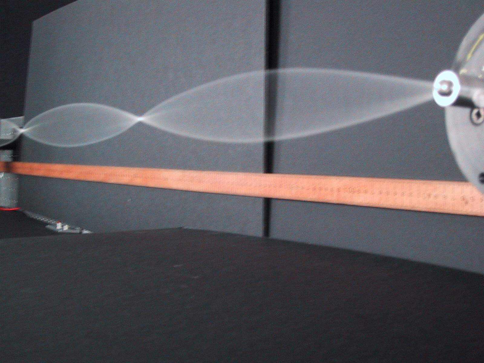
Standing waves on a string. The mechanical driver at the right is made to oscillate up and down at a resonant frequency of the string producing standing waves.
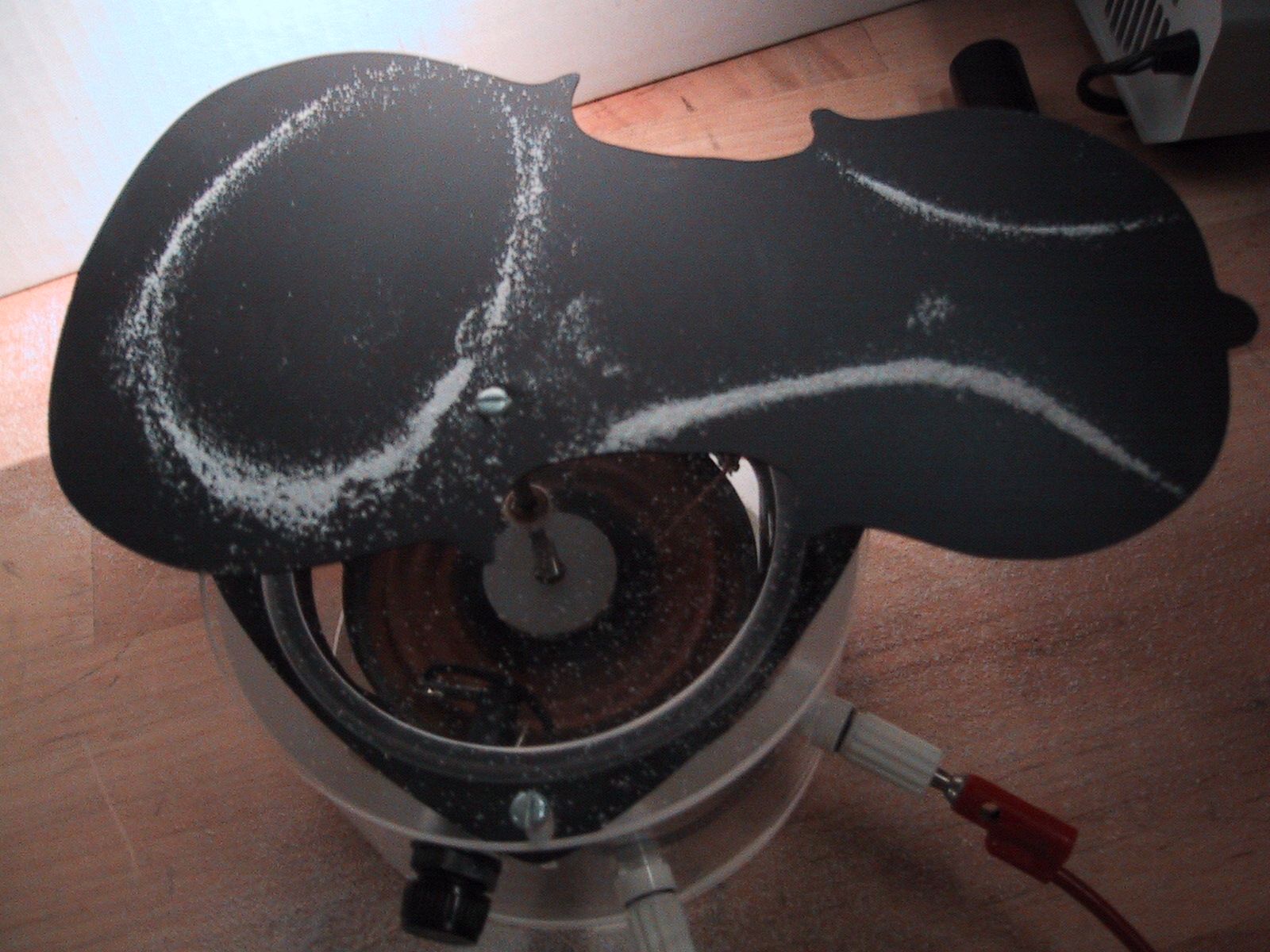
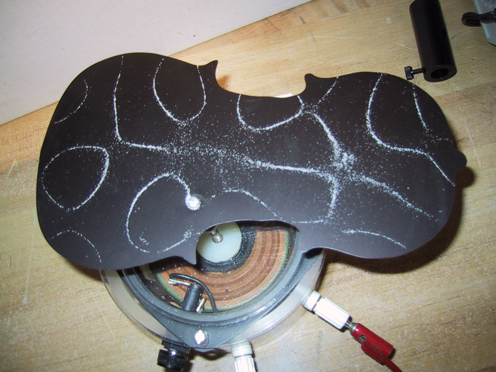
Mapping of the "nodes," or stationary lines, on the surface of a "violin" made to oscillate at two different resonant frequencies
In the case of light, of course the way to generate a reflection is by using mirrors. One instrument that uses a single source of light and generates standing waves is called a Michelson interferometer, after its American inventor. This very cleverly designed and sensitive instrument uses a partially reflecting mirror, called a beam-splitter, to break a beam of light into two separate beams. These beams are each retro-reflected and combined to interfere at a screen. One of the two retro-reflecting mirrors is fixed, but the other can be moved to shorten or extend its distance from the beam-splitter. By changing the position of this mirror, the interference on the screen can be varied from a totally constructive one (when the beams form interference maxima) to a totally destructive one. In changing from a maximum to a minimum in this way, the beam from the moving mirror has traveled an extra half of its wavelength, i.e. the mirror has translated by one-quarter of the wavelength.
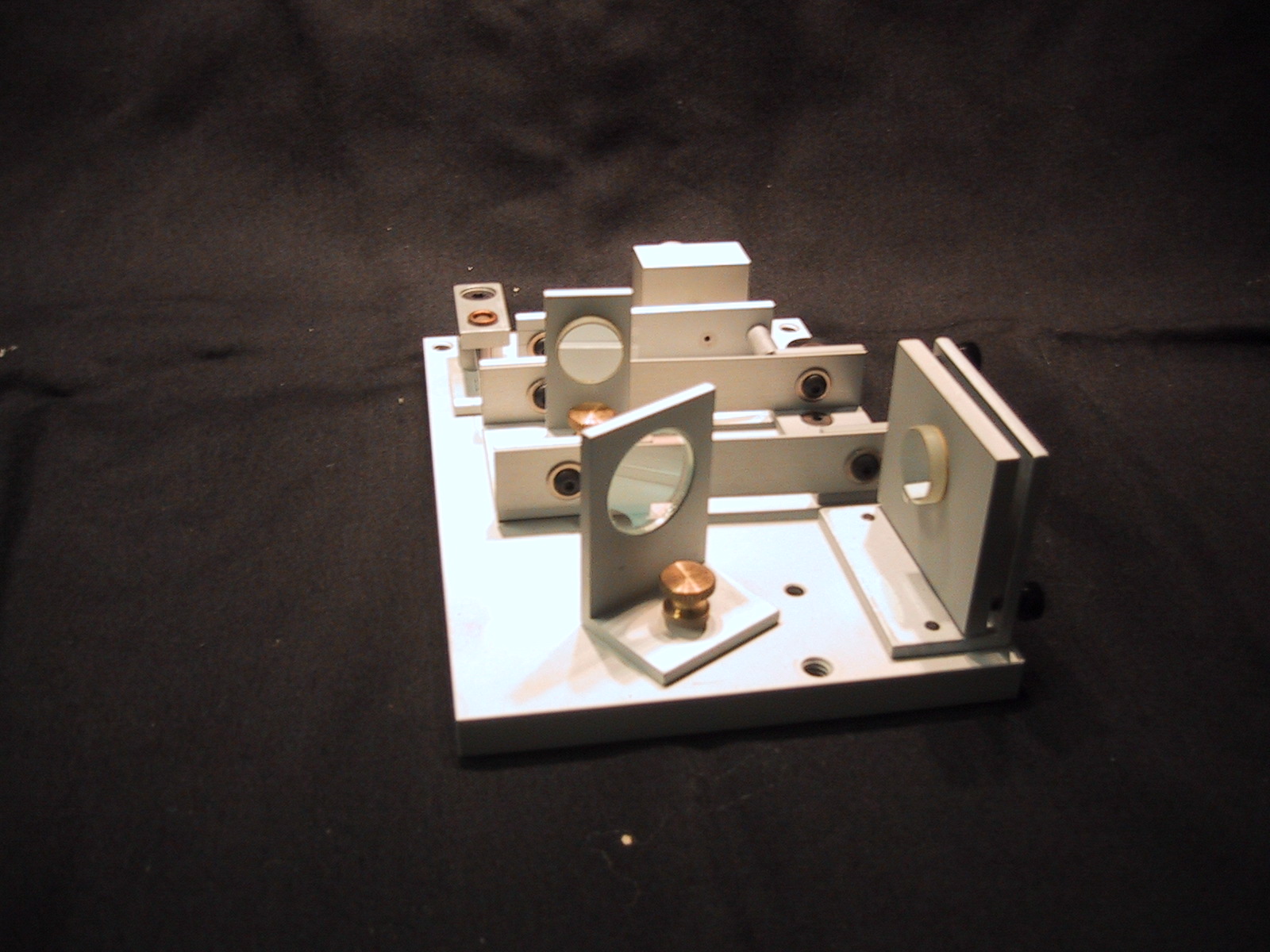
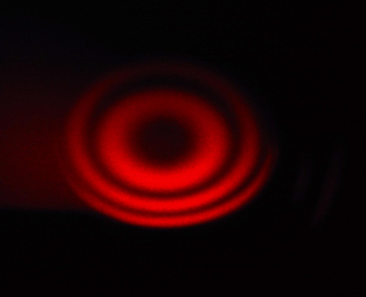
On the top is a Michelson interferometer; in the middle is a schematic of its operation; below is the pattern observed on a screen when a He-Ne laser beam is used - as the movable mirror is scanned one-quarter of a wavelength the center varies from dark to light.
Because the wavelength of visible light is about 1/100 th the thickness of human hair, the tremendous sensitivity of this instrument, equal to 1/4 of the wavelength, makes it respond to slight changes in air pressure, minute vibrations, as well as to small changes of the wavelength of the light source itself.
Another way to generate two coherent beams is to place two very small openings in front of a single beam. These openings are often in the form of very thin slits, so the interference that they produce is called "double-slit Interference". The interference pattern that the double-slit produces depends on the slit dimensions as well as on the wavelength of the light used. Specifically, to observe any interference effects at all we need slits that are comparable in size to the wavelength of the light. In addition, we need light that is in phase at the two slits, i.e. coherent light. So, this simple instrument could be used to check or verify the coherence of a given light source.
Diffraction is the property of a wave that results in bending its path of motion when the wave confronts an obstacle or just a single opening. When the size of the obstacle or opening is comparable with the wavelength, then the bent rays interfere and produce a noticeable interference pattern.
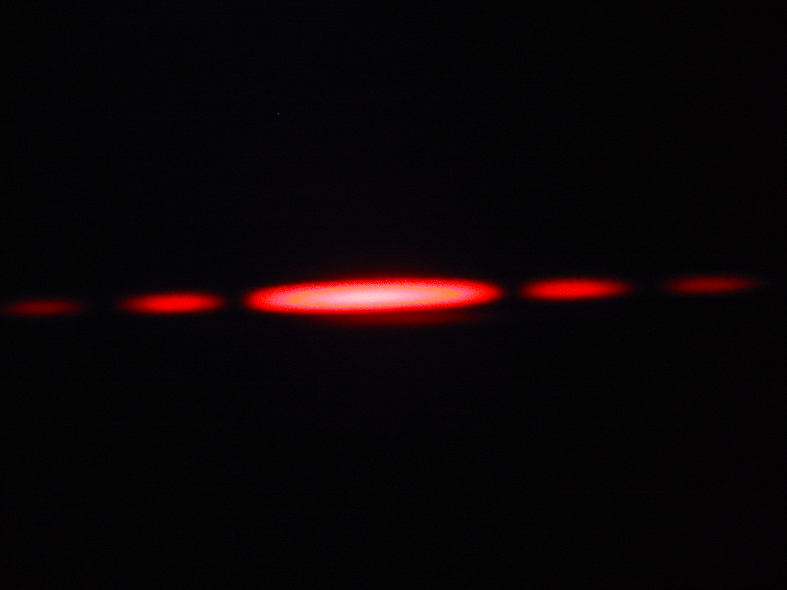
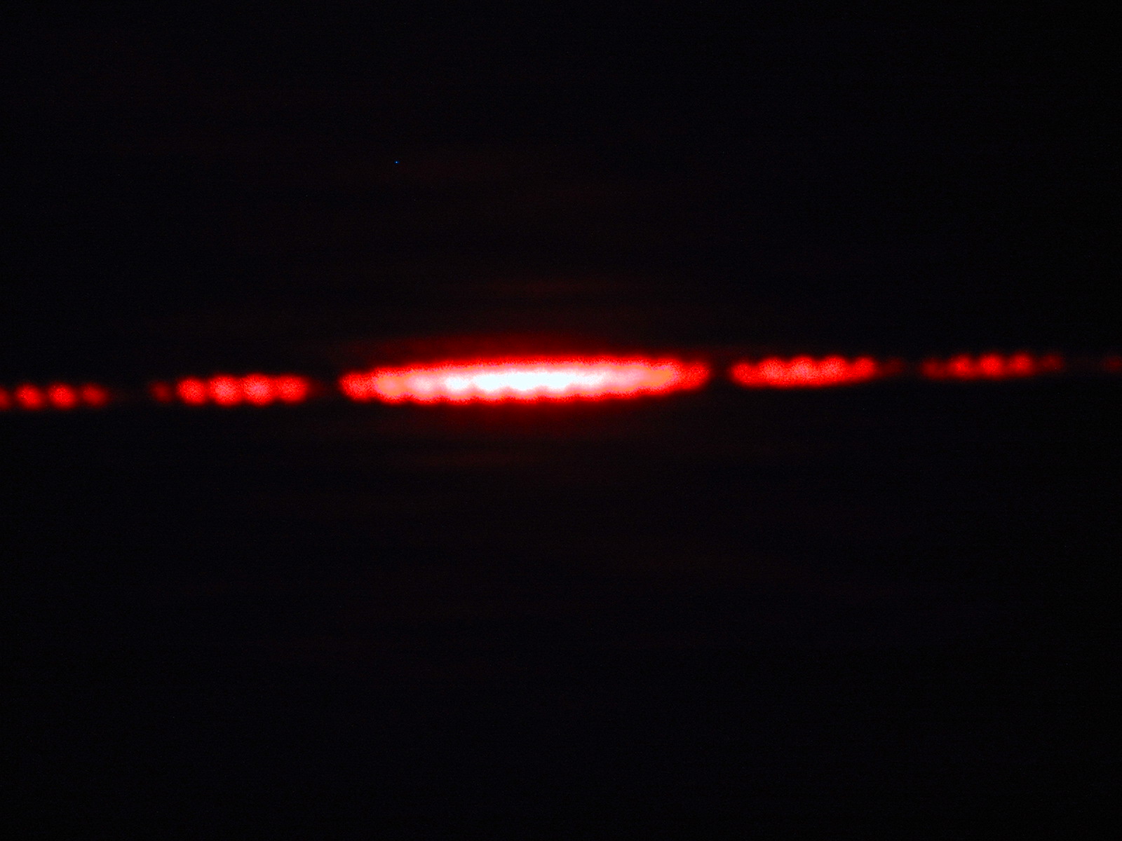
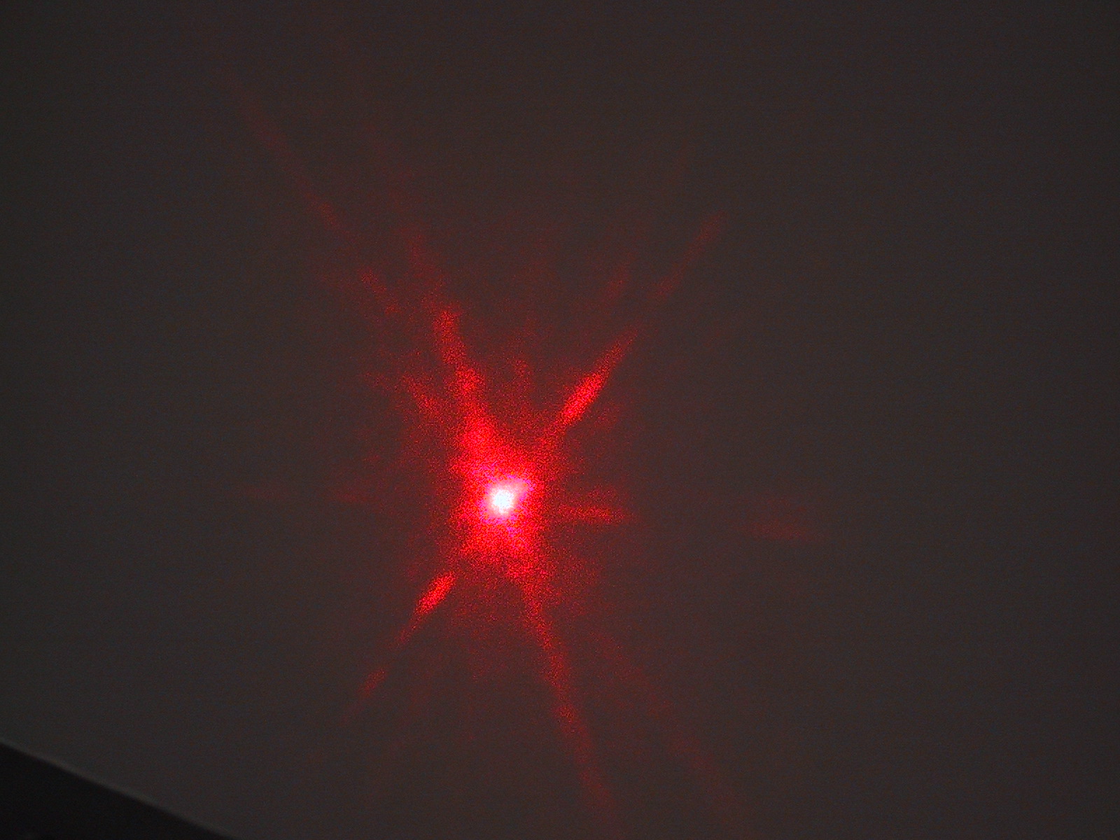
(left) The diffraction pattern of light observed on a distant screen when a He-Ne beam passes through a single narrow slit; (right) The same when the beam passes through two identical closely spaced slits. Note the sub-structure of interference within the overall single-slit diffraction pattern.
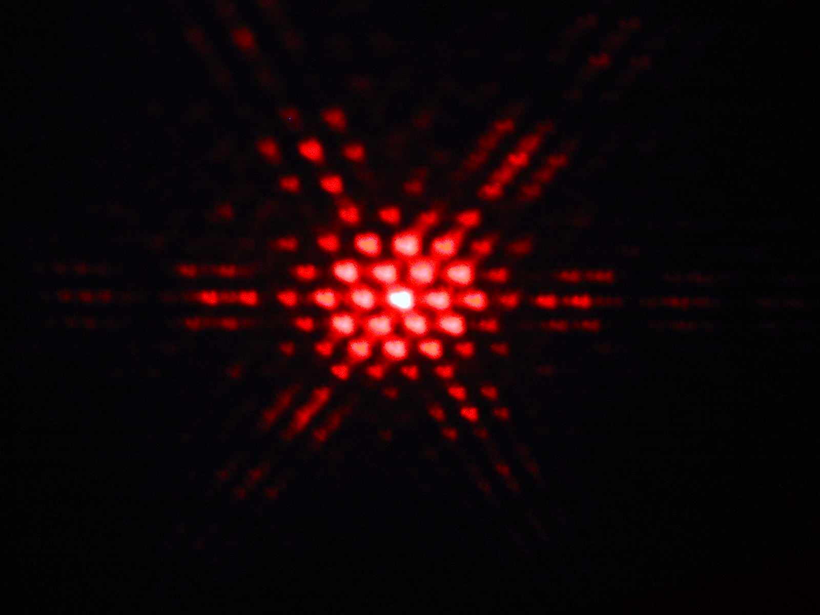
The diffraction pattern from a hexagonally-shaped hole. Note the six-fold symmetry of the pattern. Observation of such complex patterns can reveal the underlying symmetry structure of the object that diffracts the light. This is the basis for many physical techniques that study patterns in the microscopic world.
Questions on Interference and Diffraction
Polarization is another property that distinguishes waves from "non-wave" material objects. As we've seen waves come in two basic flavors: transverse and longitudinal, referring to the direction of the motion of the waving quantity with respect to the wave velocity direction. For light, or electromagnetic radiation in general, which is a transverse wave, polarization refers to the particular direction of oscillation of the electric field in the transverse plane - perpendicular to the wave velocity.
In the simplest case this direction can remain fixed, say vertically, and the light is said to be vertically polarized. This means that as the wave travels along, say horizontally, the electric field of the wave remains always vertical in direction, oscillating in magnitude. Of course, the fixed direction can lie in any direction within a plane perpendicular to the velocity - since the wave must always be transverse.
In general, the direction of the electric field may also change with time. If it changes randomly, the light is said to be unpolarized. Light from an incandescent source is unpolarized since it is produced by radiative emission from many electrons in the heated tungsten wire and there is no preferred direction along which to produce their electric field.
We can get a feeling for polarization by imagining an Etch-a-sketch toy, used to sketch line drawings using left-right and up-down knobs, that you probably all have drawn with at some time. If the drawing suface is the transverse plane and the drawing tip is made to oscillate horizontally, the "drawing" is horizontally polarized. If only the up-down knob is oscillated, the polarization is vertical. If you are good at it, you can oscillate both knobs correctly and make the drawing tip oscillate producing a straight line at any angle you want. The polarization is still said to be linear at the appropriate angle. With more skill yet, you can make the drawing tip go in a closed circle or in an elliptical path. Both of these also have analogs with light where the light is said to be circularly or elliptically polarized - the tip of the electric field arrow traveling in these orbits.
As mentioned just above, incandescent light is unpolarized. So how can light be polarized? There are four different ways to produce polarized light from unpolarized light: by absorption, refraction, reflection, or scattering.
1. Polarization by absorption: Light shining on polaroid film (not the film used in a Polaroid camera, but the kind used in Polaroid sunglasses) can be used to absorb one component of the electric field, transmitting only linearly polarized light. It works because the long polymer molecules in the film pick out a unique direction along which the electric field can be absorbed - transmitting the rest of the light oriented perpendicular to the long molecules. Connected with this is the Law of Malus, stating that the transmitted intensity I is proportional to the incident intensity Io, multiplied by the square of the cosine of the angle between the transmission axis of the polaroid film and the incident polarization direction of the light: I = Io cos2q.
Unpolarized light (with both polarizations, red and blue, lying in the transverse plane present randomly) passing through a sheet of polaroid will emerge linearly polarized along its transmission axis (shown vertically). In this and the next three figures, the red polarization direction lies perpendicular to the screen/paper.
Three sheets of polaroid are stacked one on top of another and unpolarized light is passed through. The first sheet is oriented vertically, the second smaller sheet is oriented horizontally while the third sheet is at 45o to the vertical. As you see, the second polarizer blocks all the light, while outside its shadow, the third polarizer only block part (1/2) of the light.
2. Polarization by refraction: Certain crystals have the property known as birefringence. A beam of unpolarized light passing through such a crystal will have its light along two different polarization directions travel through at two different speeds and will refract differently, so that two different beams are transmitted, each with a different linear polarization. These crystals can be polished and used as polarization devices known as crystal polarizers in optical systems.
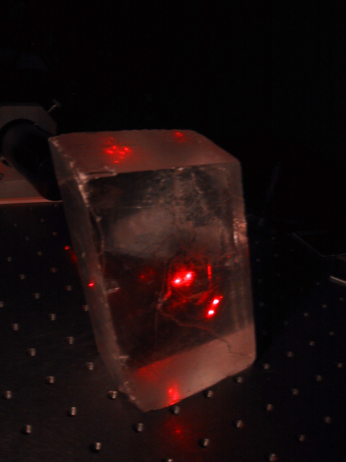
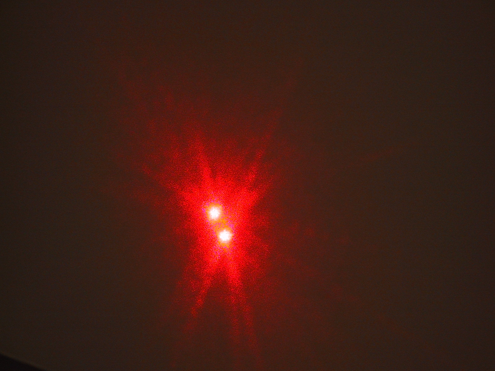
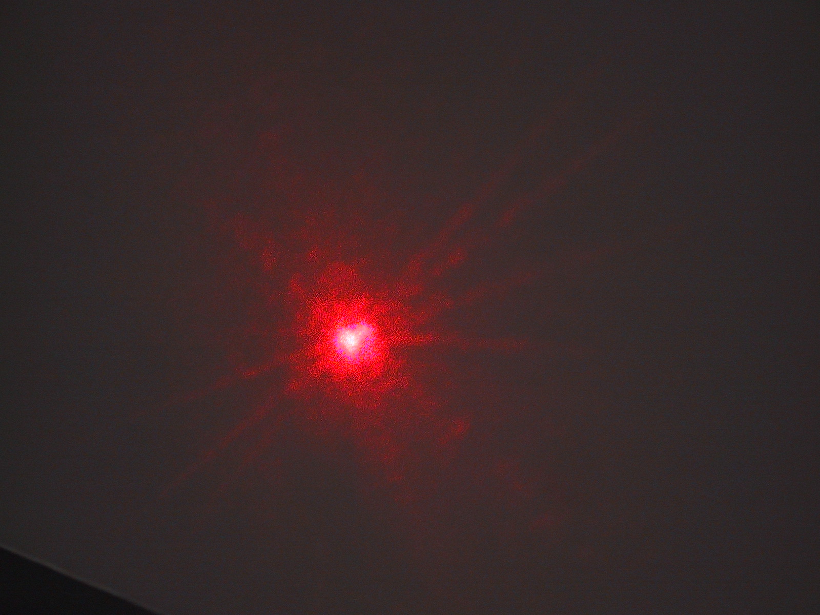
Unpolarized light will split into two beams each with a different polarization after passing through a birefringent crystal. In the photos you first see the calcite crystal with an initially unpolarized laser beam split into two beams. The second photo (on top) shows the two spots observed on a screen, while the last two show that a sheet of polaroid can be arranged to block first one and then the other beam.
3. Polarization by scattering: Light that is scattered will be partially polarized. This is because the scattered light waves must be transverse; so light that is, say vertically polarized, and that is traveling horizontally and scattered vertically cannot exist, because the vertically scattered light would be vertically polarized - but this is impossible because the light waves must be transverse and cannot be longitudinally polarized. It turns out that light that is scattered in other directions will be partially polarized.
Light scattered from the atoms in the box will be polarized because the "blue" polarization cannot travel in the direction shown due to the required transverse nature of the light wave
4. Polarization by reflection: Similar to the scattering situation, there is a particular angle of reflection from a surface at which the reflected light is linearly polarized. This incident angle is called Brewster's angle. As seen in the figure, at this angle the refracted and reflected beams form a right angle and the reflected light cannot have one of the polarizations allowed in the refracted beam because it would be along the reflected light direction. Reflected sun light from surfaces is often partially polarized when it reflects into our eyes. Polaroid sun glasses are designed to block the strongly polarized component from these reflections, thus reducing this "glare".
Light incident at Brewster's angle produces linearly polarized reflected light. Here the red arrow indicate electric fields polarized into the plane of the diagram while the blue arrows are electric fields in the plane as shown. Both need to lie perpendicular to the direction that the wave travels in.
![]()