![]()
Quantum Measurement
Measurement
Statistics & Uncertainty Estimations
Heisenberg's Uncertainty Principle
Relativity Theory & Causality
Spin, Polarization, and Mixed States
- Polarization
- Spin
- Mixed State
- Questions
Bell's Inequality
Photon Quantum Eraser Experiment
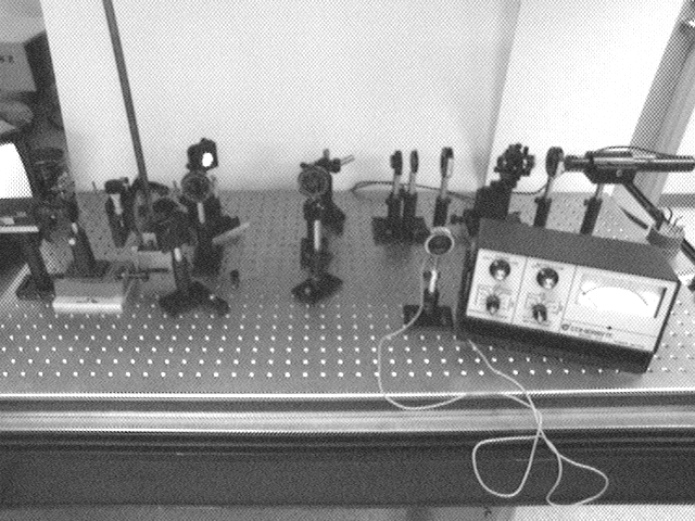
The photograph below shows the setup for the demonstration of quantum eraser as in the experiment of Mark B. Schneider and Indhira A. LaPuma (Amer. J. of Phys., 70, No.3, March 2002, pp. 266). In my setup of this experiment the apparatus consists of the following:
| Laser | Uniphase Model 1101P | (He-Ne, 1.65 mW at 633 nm) |
| Linear Polarizers | CVI Model PSP-450-750-10 | (Dichroic Sheet Polarize film, extinction: 10-4) |
| Quarter Wave Plate | CVI Model QWPM 633-05-04-R10 | (Crystal Quartz, measured circular polarization: 70%) |
| Microscope Objective | (x20) | |
| Spatial Filter | Newport Model | (3-mm pinhole & x20 Microscope Objective) |
| Lens | (f = 200 mm) | |
| Mirrors | ||
| Video Camera | Sony | |
| Power Meter | Coherent | (0.1 mW - 30 mW) |
| Breadboard | ||
| Optical States |
Procedure
After aligning the laser and the spatial filter, I set up the collimating lens to produce a "best focus" for the beam at a distance of about 4 m. I then set up and align the four mirrors of the interferometer to obtain fringes on the camera.
Next, I place the quarter-wave plate just behind the collimating lens and adjust it for best circular polarization. For this I place a polarizer after the lens and then the power-meter. This way I can monitor the laser light power for a fixed polarization direction as the axis of the quarter wave plate changes. Rotation of the polarization axis of the polarizer should result in minimum change of measured intensity when the quarter wave plate's axis is set for the best circular polarization. I adjust the axis of the wave-plate in order to achieve a minimum change in the deflection of the power-meter as the linear polarizer's axis is changed. I lock the rotation stage of the quarter wave plate, once this procedure is completed.
To "assign" the polarization in each arm I then place two plane polarizer in the arms of the interferometer. Because mirrors affect the polarization of the reflected light, I place each polarizer in the arms at the point that the light has undergone reflection from one mirror. To determine the relative direction of polarization of light in each arm I place an analyzer before the camera. With the analyzer axis fixed I first cover the beam exiting from one arm, say the right arm, and then rotate the polarizer in the other arm (left) so as to create total extinction at the camera. Then I uncover the right arm and rotate its polarizer to also achieve total extinction. At this point the beams in both arms have the same polarization. After establishing equal polarization directions in both arms I then rotate the analyzer to achieve maximum output power.
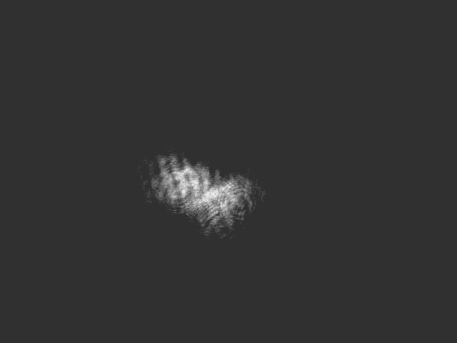
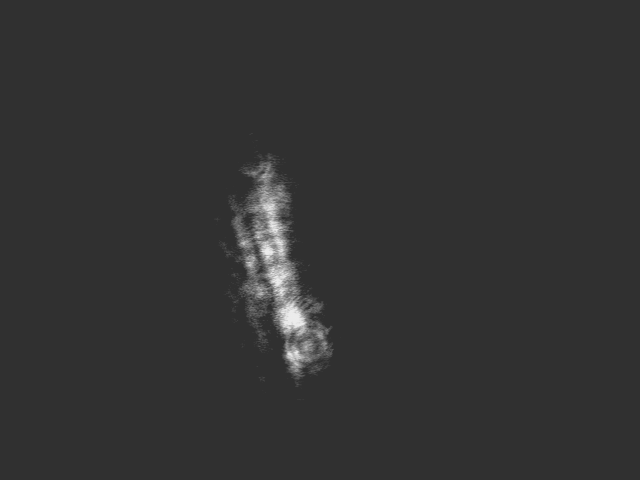
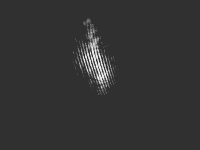
When light in each arm has the same linear polarization, interference fringes appear on the camera. Below are the camera images for the light of L-polarization for each of the two arms separately (i.e. the other arm is blocked):
|
|
|
|
Left Arm L-Polarized |
Right Arm R-Polarized |
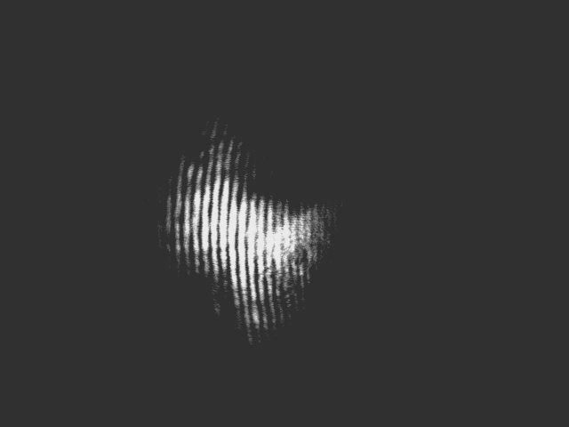
Below shows fringes that these two beams produce (i.e. when both arms are L-polarized and their shared output is combined on the camera):
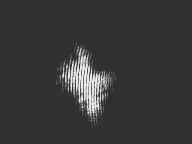
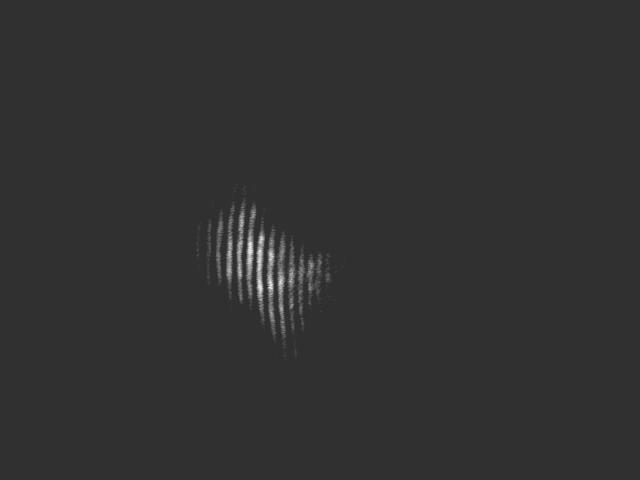
When light in both arms is, instead, P-polarized, I get the following image on the camera:
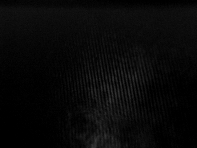
I then cover one of the arms and rotate the analyzer to distinguish the light. This arm's polarization, then is perpendicular to the polarization of light in the other arm. No fringes are visible for this cross-polarizations of the two arms. But the fringes return when the analyzer's polarization axis is at 45°:
|
|
|
The above picture on the left has the analyzer's axis at "-45°", while the one on the right has the analyzer's axis at "+45°".
Finally, I place a polarizer right in front of the laser and attenuate the laser intensity to assure that, on average, only one photon is in the interferometer. (I calculate that for this condition to hold for my spectrometer, which has an arm length of about 30 cm, the power input to the interferometer needs to be less than 0.3 mW.) The two photographs below show that we can still see fringes (similar to the two shown directly above) for these light conditions:
|
|
|

For the photograph on the left laser light intensity into the interferometer is 0.26 mW, while the intensity of the laser is reduced to its minimum possible value with the attenuator used in this setup. Still we see visible fringes. But when the analyzer's axis is oriented away from this "45°", then the fringes begin to disappear.
Contact: malekis@union.edu
Mixed Quantum States | Quantum Measurement | Department of Physics & Astronomy | Union College Home Page
Quantum Measurement © 2003 Maleki.
Last Updated: 08/13/04 02:07 PM