Scientific photos, taken years ago well before I retired. Some date from the years I tought optics, some go back to the jumioer lab course I was involved in, some came out of a course I gave in "Scientific and Technical Photography", some just came...
| |
Diffraction
Refraction is the bending of light rays as they pass from ond medium into another. This is due to the change in the speed of light (a different index of refraction) as it passes across a boundary. Diffraction is the bending of light around obstacles and into shadow regions due to the wave nature of the light. It often gives rise to "fringes", alternating regions of light and dark.
A circular aperture. If light only went in straight lines, this would look like a uniformaly illuminated disc.

|
An irregularly shaped aperture
|
Another irregularly shaped aperture.
|
Rectangular aperture.
2-fold symmetry, of course.
|
Triangular aperture. Almost
3-fold symmetry, so I guess the triangle was not quite equilateral.
|
Diffraction pattern of two narrow slits
|
Diffraction pattern of two slits, not so narrow
|
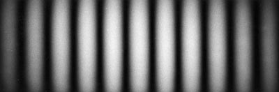
Difffraction patterns, a single slit.
These are very narrow slits, so that if the slit is narrower,
the pattern is wider. Thus the top pattern is produced
by the narrower slit. The bottom pattern is produced
by the widest slit.
|
Fringes from a Michelson interferometer. The pattern of fringes
can be thought of as the pattern resulting from in interference between
two point light sources, one in front of the other.
|
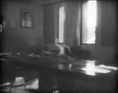
Pinhole camera. If the pinhole is too small, light diffracts into the "shadow"
regions, blurring the picture. In the first picture, the pinhole was extremely
small. Not only was the resulting photograph fuzzy due to diffraction,
but the exposurte was very long (several hours) so that fugures in the
room appear ghostly.
|
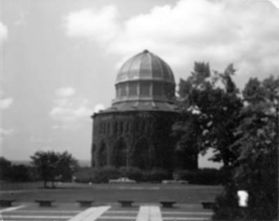
Here the pinhole was a bit too large, so the picture is fuzzy. The exposure
time was quite short, just a second or so.
 |
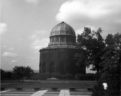
The pinhole was just right for this photograph.
 |
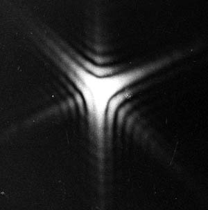
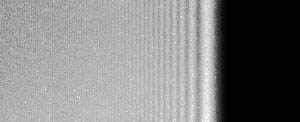
Diffraction pattern for a straight edge. In order to see this pattern,
a point source of monochromatic light is needed. That's why we
don't usually see this. Lasers make this easy to do.
|
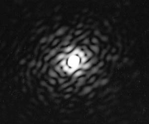
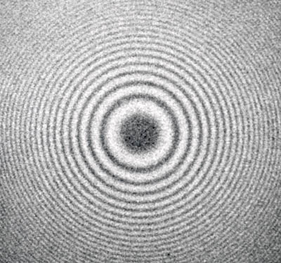
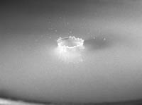
Diffraction by a circular object
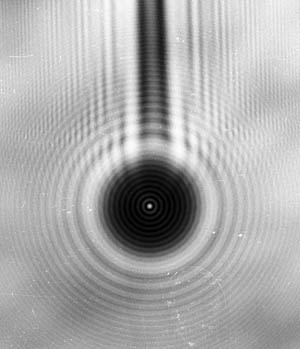
In 1818, Fresnel presented his theory
explaining diffraction of light. Poisson denied the truth of the
theory, and argued that a consequence of the theory would
be that there would be a bright spot right in the middle of the
shadow of a circular object. The spot, shown above of the
shadow of a ball bearing suspended on a needle, was
promptly discovered by Arago. This was a lot harder to do
before lasers were invented! |
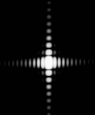
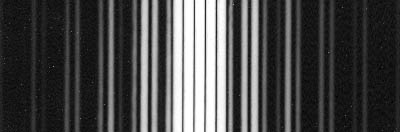
The diffraction grating
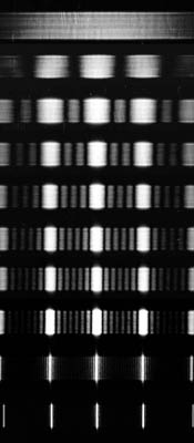
This shows the diffraction pattern of one slit, then two, then three, four,
five, six, and more. When there are many slits, we call it a diffraction
grating. The more slits, the narrower the pattern becomes. The pictures above
were taken with monochromatic light. If there were different wavelengths present,
then the interference maxima would occurr at different spots, and we would be
looking at the "spectrum" of the source. |
Solar spectrum
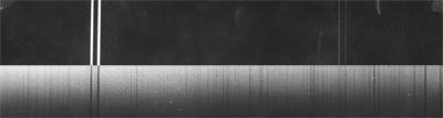
The spectrum of sunlight has missing wavelengths due to absorption of the light
as it passes through the solar at,osphere, which is significantly cooler than the
solar surface where the light was produced. In the picture above, the solar spectrum
is compared to the emission spectrum of sodium. Yes, there is sodium in the sun!
|
Another small part of the solar spectrum (lower) compared to the
emission spectrum of iron (top). There is iron in the sun.
 |
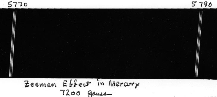
Zeeman Effect
Here is a very high resolution spectrum showing the yellow lines of the mercury
spectrum, taken when the mercury atoms were in a strong magnetic field.
This
splitting into three lines is the "normal" Zeeman effect. Most lines are not "normal".
 |
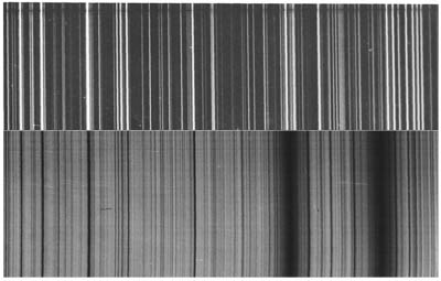
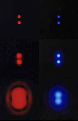
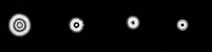
Resolving power
Images formed in a telescope of two small close sources with various
sized apertures. Large apertures at the top, small ones at the bottom.
Images at long wavelength (red) on the left, short wavelength (blue) on the right.
The ability of a telescope to resolve objects depends on both the aperture
and the wavelength used. This principle holds true not only for optical
telescopes, but for radio telescopes, microscopes, electron microscopes,
and all kinds of imaging instruments.
|
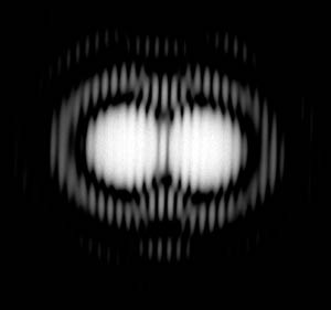
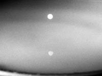
Two point sources, coherent
|
Babinet's Principle |
 |
|
and the screens used
|
|
|
Circular aprertures, Fresnel diffraction
(Not plane waves incoming; distance from aperture to screen is not large)
|
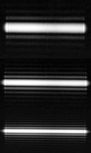
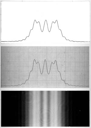
Single slit, Fresnel diffraction
Not the same as the single slit patterns shown above,
because the distances are smaller. Put another way,
not plane waves in a nd out.
Top: theoretical intensity versus position
Middle: scan of the pattern below
Bottom: the pattern as recorded on film
|
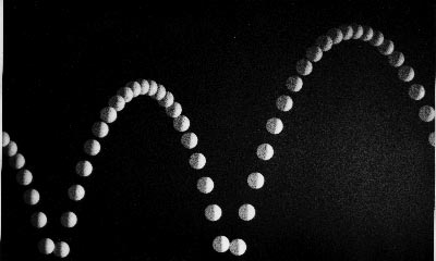
Strobe photos
Bouncing ping pong ball
|
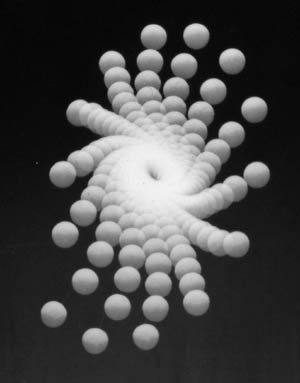
Conical pendulum, seen from below.
Styrofoam ball on a string.
|
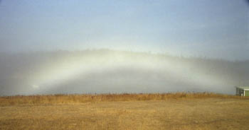
Bows
Rainbow

Maine
|
Fogbow
Same thing, but the sroplets are much smaller, so diffraction takes place.
|
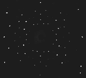
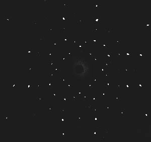
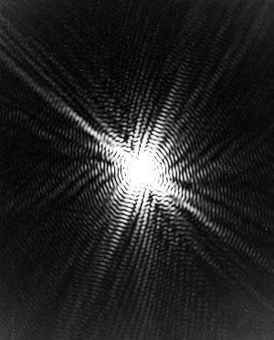
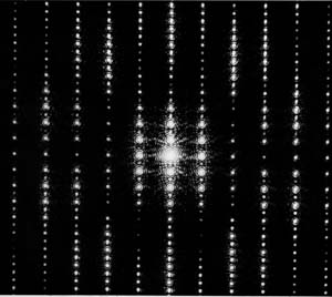
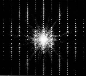
X-rays
In Laue patterns, x-rays with a continuous spectrum are scattered from a single crystal.
X-rays: Laue pattern. The film formed a cylinder around the target crystal.
A continuum spectrum of x-rays on a single crystal.
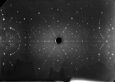
X-rays: Laue diffraction pattern
for a single Si crystal.
The film wraps around the sample, so that it covers
nearly 360 degrees.
There is a (111) crystal direction right in the center.
|
|
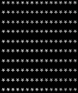
Powder patterns
Monochromatic X-rays (a single wavelength, copper K-alpha) are scatrtered by many very small crystals
with random orientations with respect to each other and the x-ray beam.
|
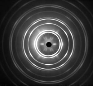
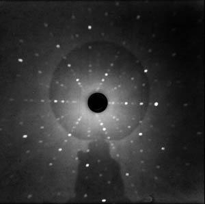
Forward scattering from an aluminum wire (many small crystals).
The dark circle in the center was from a lead plug used to stop the unscattered x-ray beam.
The "X" patterns in the center are due to a partial alignment
of the crystals of aluminum in the extrusion process when the wire was fornmed.
|
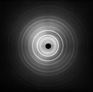
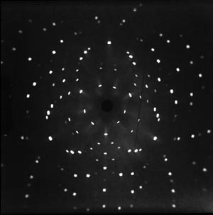
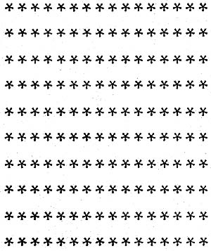
Forward scattering from finely ground NaCl.
No x-patterns in the center, of course. |
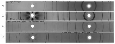
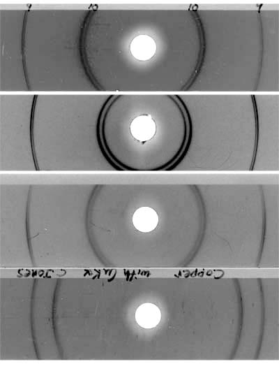
Powder patterns, cylindrical camera
Scattering from "powder" Ag, Al, Au, and Cu.
The film is wrapped around the sample, and so forms a cyminder. The x-rays
enter from the hole on the right, and exit from the hole of the left.
|
Backward scattering (the x-ray entrance hole) detail.
The resolving power gets very high in the backward direction, the
"doublet" patter is from the fine structure in the x-ray spectrum:
the copper K-alpha-1 and K-alpha-2.
 |
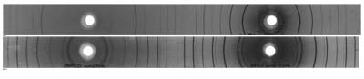
Wrap-around powder patterns for NaCl and KCl, similar but not the same.
KCl is about as close as you can get to a simple cubic pattern!
|
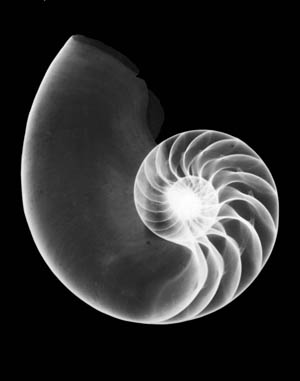
Logarithmic spiral:
X-ray of chambered nautilus shell
|
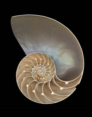
Chambered nautilus shall, cut in half
|
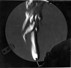
Schlieren photography
It's all done with mirrors and a straight edge.
|
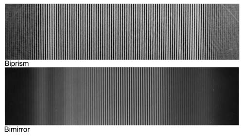
Biprism and bimirror to produce fringes simiklar to the double slit.
|
Liquid drop falls into a liquid
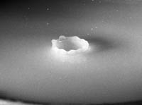
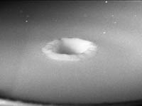
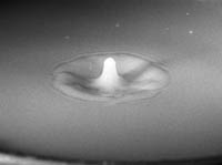
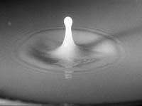
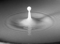
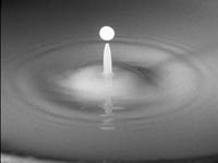
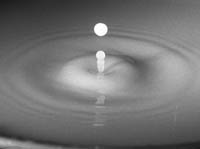
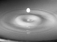
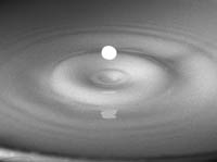
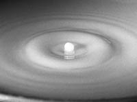
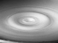
... and wait for the next drop to fall. These were still photographs, each of a different
drop, but the events are very much the same from drop to drop. A bit of milk was
added to the water to make the drops more visible. That worked fine, except it
got stinky after a while. The falling drop interrupted a laser beam, which triggered
a variable delay circuit, which triggered the strobe.
|